Please note that I cover the creation of these challenges in this article.
Covered challenges
- Trop d’IQ - intro
- Space Radio - easy
- R16D4 - easy
- Comment est votre température ? - medium
- Code Radiospatial n°1 - medium
Trop d’IQ
Level : Intro
Context
The goal of this challenge is to retrieve the original signal from an IQ file. Moreover, the given file doesn’t contain the signal itself but its Discrete Fourier’s Transform (DFT).
This challenge was designed to introduce the IQ format and the Fourier Transform because they are the foundation of the signal analysis and radio frequencies at a software level.
Solve
Once the file is downloaded, we first need to load it properly :
import numpy as np

# According to the description, the format is IQ awith Complex128
array = np.fromfile("chall.iq", np.complex128).astype(np.complex128)
Once the signal is loaded, we then need to apply the inverse what the DFT did to the original signal. To do that, we need to apply an Inverse Discrete Fourier Transform and then get the magnitude. We can use for example the module scipy.fft.ifft :
from scipy.fft import ifft

i_array = ifft(array)
data = np.abs(i_array)
Once this is done, if we try to listen to the obtained signal, we should be barely able to hear it. But why is there so much noise ?
Well, we can see the thing in the following way : we know that the sampling frequency is at 44.1kHz, so the first half of the fourier transform coefficients will represent the frequencies between 0-22kHz, the other half between 22-44kHz. We don’t need the second half because we can’t hear it, the first thing to try is just to set the second half of the coefficients to zero : this is improving the quality of the audio. This sounds like a human voice, we may decide to juste set to zero more coefficient to remove high frequencies of we can also use a band-pass filter between 300Hz to 3kHz because these frequencies contains the most important informations about a human voice.
To filter that easily, the best thing is to work on the DFT coefficients rather than the signal ones. All in all, the final script should look like this :
import numpy as np
from scipy.fft import ifft
from scipy.io.wavfile import write
array = np.fromfile("chall.iq", np.complex128).astype(np.complex128)

# Filter before iFFT
# Set to zero all coefficient after
# the first quarter = low pass filter
# with cutoff frequency of approx. 10kHz
array = np.concatenate((array[:n//4], [0] * (3 * n//4)))


i_array = ifft(array)
data = np.abs(i_array)

# Convert it back to wav file
data_s = data.astype(np.uint16)
write("out.wav", rate, data_s)
ifft(array).tofile()
Useful resources
Space Radio
Level : easy
Context
This challenge is designed to be the continuity of the first challenge. The goal of this one is to perform a frequency demodulation.
There is many ways to achieve this, here are some :
Solve
What I would advise for a beginner is to do it “manualy” with python, because this allows you to really understand what you’re doing. For more people more familiar with this, one may choose QGRX for its simplicity compared to Gnu Radio (way more powerful but also complicated). There are many examples of python code that performs FM demodulation. I will use GQRX.
Luckily, GQRX handle IQ files. Here are the steps :
- Import the file in GQRX :
- For Device select Complex Sampled IQ file
- In the Device String, enter the path to your file at the location /path/to/your/file
- For input rate, use the one given in the description i.e 48kHz
- On the right panel, then go to Receiver Option to access demodulation parameters
- Select the frequency of 0 this means that the carrier frequency is 0 (this can be confirmed if we take a look at the spectrum displayed when we click on play : the spectrum is zero-centered)
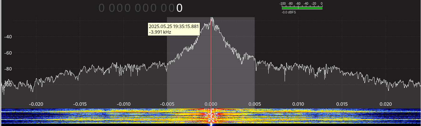
- Select the mode Narrow FM
- Select the frequency of 0 this means that the carrier frequency is 0 (this can be confirmed if we take a look at the spectrum displayed when we click on play : the spectrum is zero-centered)
Then click on play and you should hear the signal.
R16D4
Level : easy
Context
We are given an electronic schematic, some voltages of the inputs of this schematic and also an Arduino board code. The goal is to understand what this schematic does in order to retrieve the LEDs state from the input voltages given.
Here is the schematic

And the Arduino board’s code :
int value = 0;
int input_pin[16] = {0, 1, 2, 3, 4, 5, 6, 7, 8, 9, 10, 11, 12, 13, A6, A7};

void setup() {
  for(int i = 0; i < 16; i++) {
    pinMode(input_pin[i], INPUT);
  }

  pinMode(A0, OUTPUT);
  pinMode(A1, OUTPUT);
  pinMode(A2, OUTPUT);
  pinMode(A3, OUTPUT);
}

void loop() {

  value = -1;
  for(int i = 0; i < 16; i++) {
    if (digitalRead(input_pin[i]) == HIGH) {
      value++;
    }
  }

  if (value & 1) {
    digitalWrite(A3, HIGH);
  } else {
    digitalWrite(A3, LOW);
  }

  value = value >> 1;
  if (value & 1) {
    digitalWrite(A2, HIGH);
  } else {
    digitalWrite(A2, LOW);
  }

  value = value >> 1;
  if (value & 1) {
    digitalWrite(A1, HIGH);
  } else {
    digitalWrite(A1, LOW);
  }

  value = value >> 1;
  if (value & 1) {
    digitalWrite(A0, HIGH);
  } else {
    digitalWrite(A0, LOW);
  }

  delay(10);
}
Solve
In a nutshell, the board’s code first compute the number of activated arduino’s input PINs, let call this number $v$. It will then power on the LED $D_i$ if the i-th bit of $v$ is set to one, otherwise it will power it off. To know what diodes will be activated, we need to know the values at the input pins.
Let’s take a look at the schematic. By looking at it, we can see that there is exactly 16 Operational Amplifiers (op-amp) that are used as comparators (take a look at this wikipedia page to see some circuits based on op-amp).
In a nutshell, if the voltage at the non-inverting input (+) is greater than the voltage at the inverting input (-) then the voltage at the output of the op-amp will be equals to the positive power supply voltage, otherwise the output voltage will be equals to the negative power supply voltage (0V here). To compute efficiently the voltage at the inverting input of each amplifier, one can see each inverting input as the middle of a voltage divider. If there is $n$ resistors between the considered inverting input and the ground then the voltage at this point will be : $VCC\times\frac{m}{16}$. Furthermore, one can note that if an op-amp outputs VCC, then all the op-amp “below” on the schematic will also output VCC.
Lets compute how many op-amp outputs a voltage of VCC for every given voltage :
- $VCC \times \frac{7}{16} < 2.34V < VCC \times \frac{8}{16}$ : 7 op-amps ouputs the VCC voltage -> LEDs 1, 2 and 3 are on
- $VCC \times \frac{12}{16} < 3.9V < VCC \times \frac{13}{16}$ : 12 op-amps ouputs the VCC voltage -> LEDs 3 and 4 are on
- $VCC \times \frac{1}{16} < 0.47V < VCC \times \frac{2}{16}$ : 1 op-amp ouputs the VCC voltage -> LED 1 is on
- $VCC \times \frac{2}{16} < 0.78V < VCC \times \frac{3}{16}$ : 2 op-amps ouputs the VCC voltage -> LED 2 is on
- $VCC \times \frac{14}{16} < 4.52V < VCC \times \frac{15}{16}$ : 14 op-amps ouputs the VCC voltage -> LEDs 2, 3 and 4 are on
- $VCC \times \frac{9}{16} < 2.96V < VCC \times \frac{10}{16}$ : 9 op-amps ouputs the VCC voltage -> LEDs 1 and 4 are on
Note that this circuits acts like an analog to digital converter on 4 bits, but integrated circuits are used instead of micro-controller. Moreover, there is better designs of analog to digital converter.
Comment est votre température ?
Level : medium
Context
The challenge’s goal is to retrieve informations exchanged between an Arduino board and a SHT40 sensor over I2C. More precisely, we have to find what’s the serial number of the sensor and both temperature and humidity.
I cover the creation of this challenge on this article.
Solve
To solve this challenge, one may parse the signal of the I2C bus and then code a decoder in any language, or use some tools that are already existing. While for beginers I would recommend to solve this challenge using the first way in order to understand well the I2C protocol, it’s way faster to use some existing tools.
What I will use is pulseview which is a very powerful software to decode many protocols. Some online datasheet of the SHT40 sensor will also be useful to solve this chall.
Once the data is loaded in PulseView, I add the I2C protocol decoder, the first line it the SCL and the second one is the SDA. This can be guessed kinda easily by looking at the signal on each line : the signal on the first one is mostly periodic which indicates that it should be the Serial Clock Line. I got 4 series of I2C packets, that I will analyse one by one.
The main parts of the sensor’s datasheet that I will use will be the Table 7 that gives informations about available commands and the part 4.5 that shows how to get the temperature and humidity from the I2C exchange.
First part of the exchange
Here is the first part of the exchange between the board and the sensor :
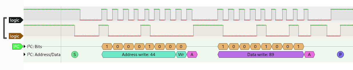
We can see that :
- There is an address write packet to the address
0x44(according to the datasheet, this is the default I2C address of the sensor) - The next packet should be the command sent to the sensor (acc. to datasheet) which is
0x89i.e theread serialcommand (see datasheet)
So, this first part is the board, sending to our sensor the command to get the serial number of the sensor, we should have the sensor response in the next part of the exchange. Note that according to the datasheet of the sensor, the sensor’s response should be 6 bytes long (incl. the CRCs).
Second part of the exchange
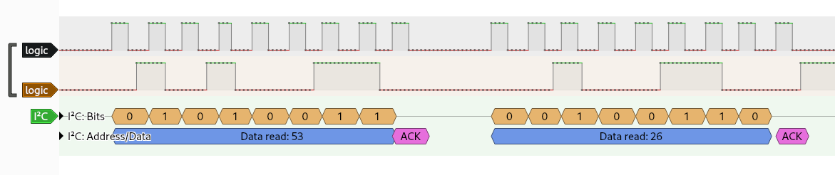
Here is the second part of the exchange between the board and the sensor :
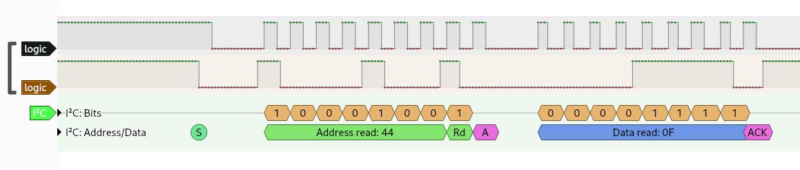
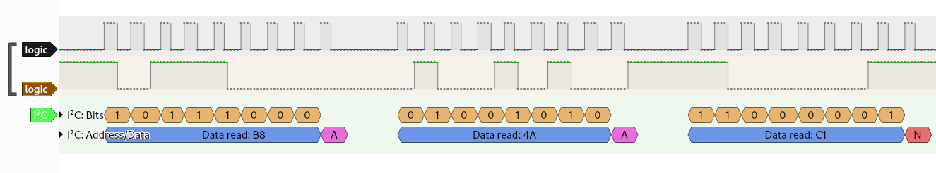
If we look at the diagram given in the datasheet about a typical I2C exchange :
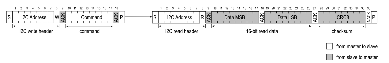
We can see that the adrress read packet is from the board, and then the next packets are the response of the sensor : 2 packets of data and then 1 packet of CRC. So, we have the following informations :
- first bytes of SN :
0x0FA8 - CRC :
0x5D - last bytes of SN :
0xB84A - CRC :
0xC1
So, the first part of the flag should be : 0fa8b84a.
Third part of the exchange
Here is the third part of the exchange :
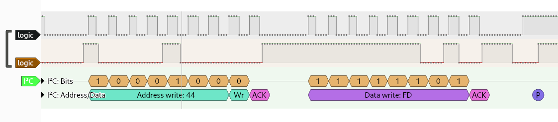
This time, the board is sending the command FD over I2C which is according to the datasheet measure T & RH with high precision (high repeatability) and the length of the response should be 6 bytes.
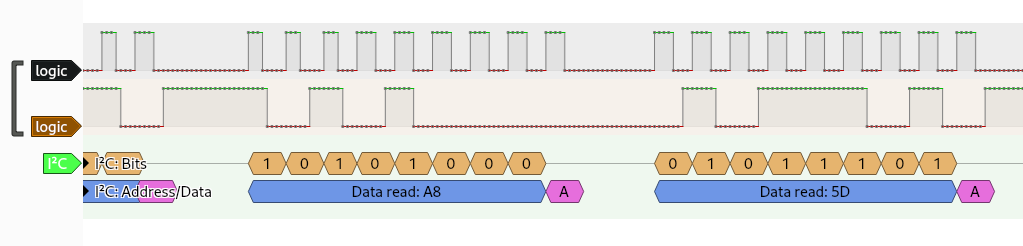
Fourth part of the exchange
Here is the last part of the exchange between the board and the sensor :
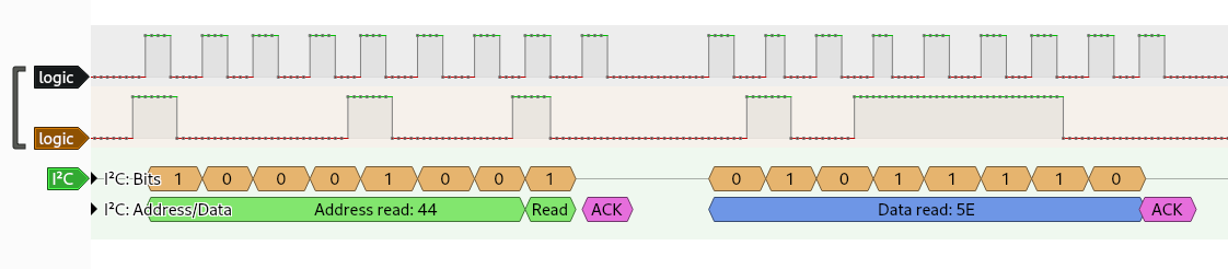
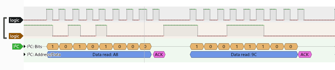
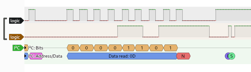
From that exchange, we have that :
- The raw temperature is
0x5e53 - The raw humidity is
0xa89c
From the datasheet, we have to do the following conversions to get the real temperature/humidity :
\[T = -45 + 175\times\frac{T_{raw}}{2^{16} - 1}\] \[RH = -6 + 125\times\frac{RH_{raw}}{2^{16}-1}\]So, we finaly got :
- $T = 19.48\degree C$
- $RH = 76.33\%$
All in all, the flag is then 404CTF{0fa8b84a|19|76}
Code Radiospatial n°1
Level : medium
Context
The goal of this challenge is to retrieve data from a POCSAG transmission.
Solve
I’ll use [GQRX](GQRX and sox. The idea is to use GQRX to parse the IQ format and open an UDP server. Then multimon-ng read the samples from the UDP server and decode the POCSAG. One can also do it by hand, this is feasible because it’s the way I used to create this challenge.
GQRX
First, let’s start GQRX in the same way as described in the writeup of Space Radio. In addition, let’s start the UDP server : go to “Input Control” and enable the server.
We need to find the carier frequency, which is the peak at 135kHz. The filter width and the shape, can be set as normal and the mode has to be set one Narrow FM.
Multimon-ng
Now, lets decode the POCSAG packets !
First, we need to retrieve the samples from the UDP server : nc -ul 127.0.0.1 7355
Then, we have to convert the samples in the right format in order to be decoded correctly by multimon-ng : sox -t raw -esigned-integer -b16 -r 48000 - -t raw -esigned-integer -b16 -r 22050 -
Finaly, we can decode the POCSAG packets :multimon-ng -t raw -a POCSAG512 -a POCSAG1200 -a POCSAG2400 -f alpha -e --timestamp -
Explanation of the last command :
-t raw: we got the input samples in raw format-a POCSAG512 -a POCSAG1200 -a POCSAG2400: we enable the decoding of POCSAG packets for rates 512, 1200 and 2400 bauds-f alpha: we decode the data of the packets as alphanumerical characters (the encoding is different if we send only digits via POCSAG)--timestamp: add a timestamp to the decoded packet (not mandatory)
Then we got :
user@linux: ~$ nc -ul 127.0.0.1 7355 | sox -t raw -esigned-integer -b16 -r 48000 - -t raw -esigned-integer -b16 -r 22050 - | multimon-ng -t raw -a POCSAG512 -a POCSAG1200 -a POCSAG2400 -f alpha -e  --timestamp -

multimon-ng 1.2.0
  (C) 1996/1997 by Tom Sailer HB9JNX/AE4WA
  (C) 2012-2022 by Elias Oenal
Available demodulators: POCSAG512 POCSAG1200 POCSAG2400 FLEX FLEX_NEXT EAS UFSK1200 CLIPFSK FMSFSK AFSK1200 AFSK2400 AFSK2400_2 AFSK2400_3 HAPN4800 FSK9600 DTMF ZVEI1 ZVEI2 ZVEI3 DZVEI PZVEI EEA EIA CCIR MORSE_CW DUMPCSV X10 SCOPE
Enabled demodulators: POCSAG512 POCSAG1200 POCSAG2400
2025-06-05 14:40:32: POCSAG1200: Address: 1874448  Function: 3  Alpha:   Voici le flag : 404CTF{fb31e1acc2e6eae8be01182d3029ffcb958e3368ca991ceb53895b8c97f2f275}
Unidentified Serial Bus [1/2]
Level : medium
Context
We have